H bridge mosfet driver driver#
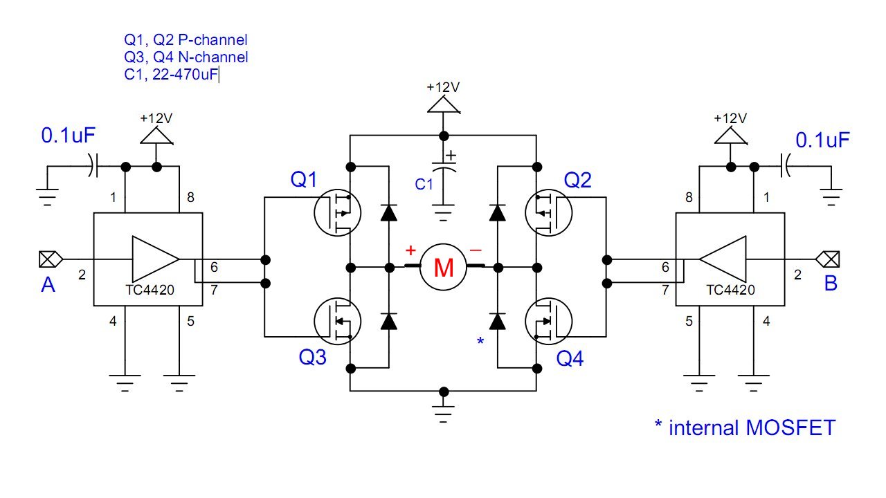
Also it is not clear why do you use gate pull-down resistors, the driver needs more current to turn MOSFET on, so not very clever idea. I do think you are wrong, but you can prove otherwise with a scientific article or application note where this is described. The diode and resistor also adds unwanted resistance and capacitance in the gate circuit. This will generate a voltage drop on R that will turn the MOSFET on again. When the M1 closes, the whole recirculating current, at first moment would pass through those R/D because the schottky diode has lower forward voltage than intrinsic diode of the MOSFET. As you can see, a recirculating current could even turn on the MOSFET when it should be off. First is not clear aboutt the function of diode and resistor on AHS, BHS gates. Simulate this circuit – Schematic created using CircuitLab This avoids the 'floating' problem, and is more efficient because the body diodes are bypassed most of the time. This problem can be solved by keeping Q2 turned on and applying 'half-bridge' drive to Q3 and Q4.
H bridge mosfet driver generator#
Due to the fast back-emf decay the bootstrap capacitor doesn't have much time to charge, and it gets less at higher PWM ratio as the motor speed increases and produces more generator voltage which reduces the back-emf conduction time. If it rises above ground then the charged voltage will reduce (to zero at ~11.4 V). Here we see that the back-emf conduction period in this 'fast decay' mode is less than 1 μs.:-ĭriver bootstrap capacitor C2 charges through D2 from +12 V, but only when the FET Source (node BHS) is close to ground. This is clearly visible in your "50% PWM 128 kHz" scope image. From then on the undamped inductance and parasitic capacitance create a decaying oscillation as the rest of the magnetic energy is dissipated. At this point the body diodes turn off and the motor is effectively 'floating'. The flywheel current rapidly removes energy from the windings, until the back-emf voltage drops below the supply voltage. When the motor is spinning the effective voltage that the back-emf needs to overcome is even higher because the motor is generating a positive voltage which subtracts from it. That means that during the PWM "on" period, the motor receives powerĭuring the 'off' period, back-emf produced by the motor windings creates a negative voltage that increases until it reaches the supply voltage and turns on the body diodes of Q1 and Q4. Presently I am only driving one half of the bridge with PWM, Q2 & Q3. The test setup and all of the traces are explained in the attached image (note that DISABLE is grounded during trials to enable the H-bridge driver).Įdit: Vmot_ret & ground are tied, even though this is not shown in the schematic. The Vgs problem appears at a lower duty cycle in the 32kHz setup, presumably because the motor is able to accelerate more in the longer on-times with the lower PWM frequency. The attached image shows the circuit I am using, as well as several scope traces for various PWM duty cycles at two different PWM frequencies (32kHz & 128kHz). However, before I start blowing FETs I would like to get some input from others.

I think the problem will go away once I drive the bridge in complimentary mode, as the FETS that are on in minority portion of the PWM cycle will provide a path for motor regeneration, clearing the way for the next majority portion of the cycle.

Eventually Vgs drops enough that Q3 won't even turn on any more and the bridge starts "hiccuping". As motor speed increases, Vgs on the high-side FETs drops, presumably due to motor regeneration during deceleration in the "off" portion of the PWM signal. However, I am experiencing an interesting problem. Again, for now I am just PWMing Q2 & Q3 and leaving Q1 & Q4 off. That is, Q2 & Q3 on together in the "on" portion of the PWM signal, then Q1 & Q4 on together in the "off" portion of the PWM signal. I have provisions in the controller for this bridge to drive it in complimentary mode. That means that during the PWM "on" period, the motor receives power and during the "off" period it coasts. I have not yet fitted RC snubbers across the FETs (although my board has pads for them, I just need to characterize the board to calculate part sizes), nor have I added any bypass capacitors across the motor (C8-C10 in the attached schematic). The bridge is implemented with discrete DPAK N-channel MOSFET transistors driven by an HIP4081AIBZ.

I am developing an H-bridge for use with 48VDC brushed motors.


 0 kommentar(er)
